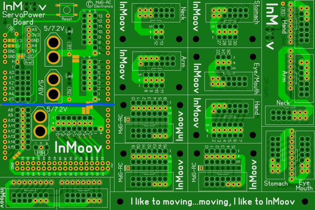
This is a tutorial for the Nervo board assembly.
Notice that some picture used are for a previous model, that means your board will be a bit different. Also this tuto is explaining how to assemble the Nervo board for a Arduino Mega.
The Nervo board for the Arduino Uno is almost the same but you need to cut the Nervo board on the blue section line.
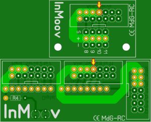
Beware, The very first batch of boards (18 boards in total produced and sold before 17/02/2015)are concerned. Please read carefully bellow what Marten says. The arm connector is sometimes causing shortcut, depending on how it is welded.
« The PCB causing issue had a white Silkscreen Text « CE MdG-RC »
Just in case, to avoid possible shortcut, you have to de-solder two Male pins from the Male-Connector or not weld them at all ».
We are very sorry for those of you that need to de-solder the pins.
Okay now, lets begin:
STEP1
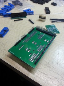
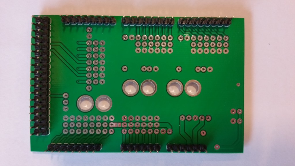
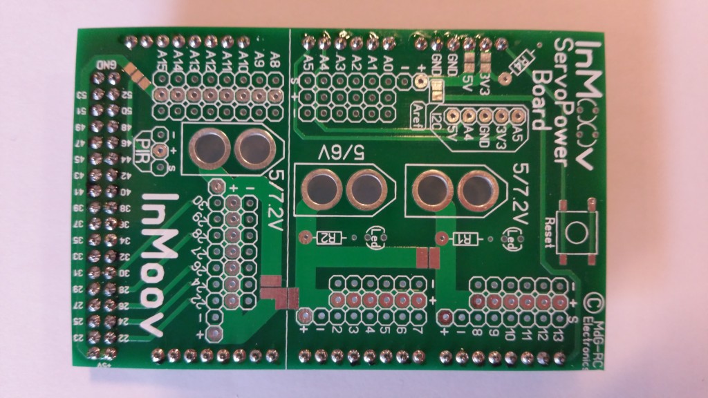
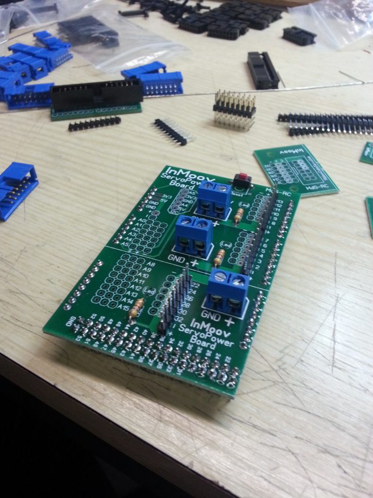
Start by adding and soldering all the headers on the bottom necessary to fit to the Arduino Mega board.
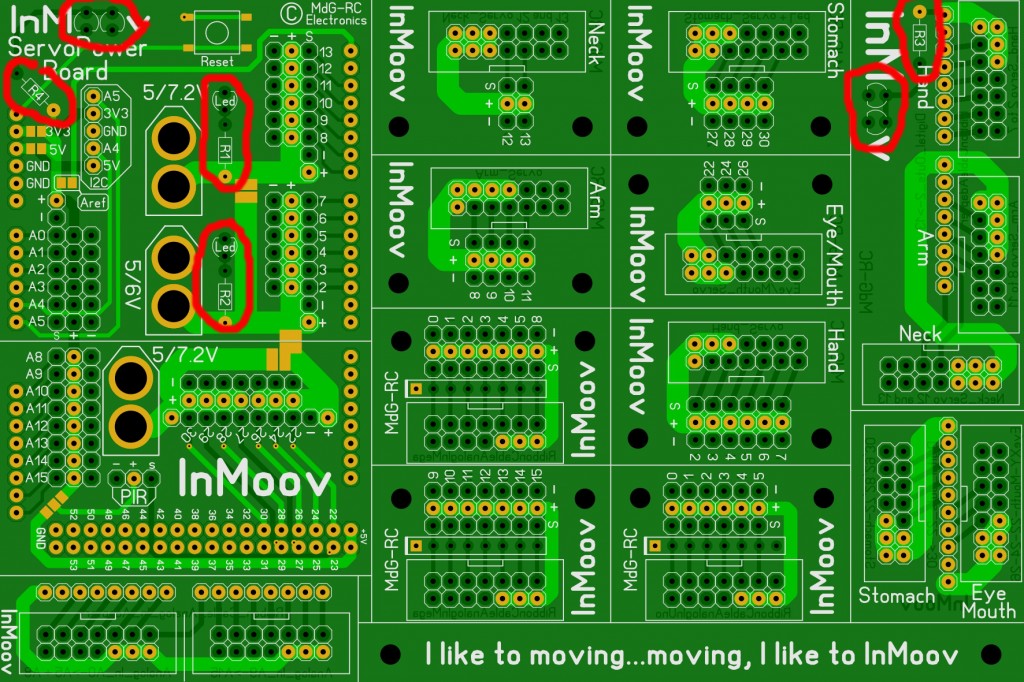
STEP2
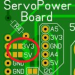
Notice the red location dots, if you plan to use the same voltage for all the servos you will need to bridge by soldering these spots. In another words, if you want to have different voltage for your servos, don’t bridge them but add extra XT60 connectors. You can have up to 3 different voltage.

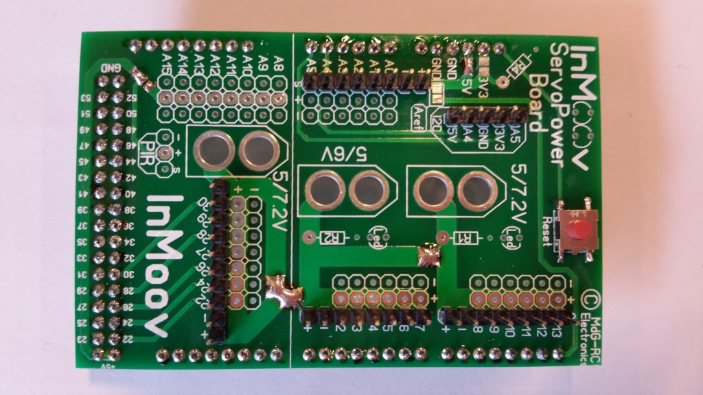
If you want only one voltage for all the servos solder bridges like this:
If you like to use the 3.3V regulator from the Arduino you need to solder all solder-jumpers as showed in this picture:
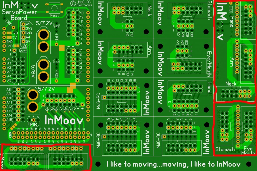
STEP3
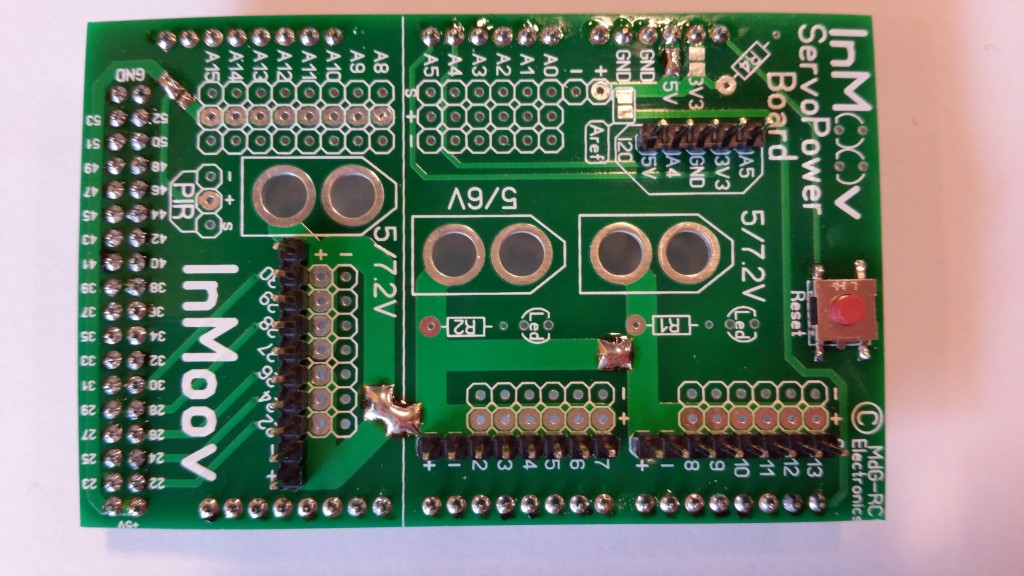
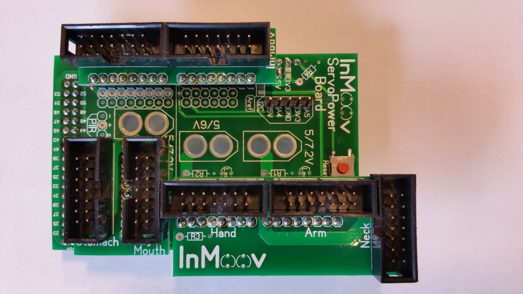
Add and solder the headers on the top of the Nervo board as shown on the picture. This will be to add the upper boards later. Also solder connect the powers if you plan to use the same voltage for all the servos.
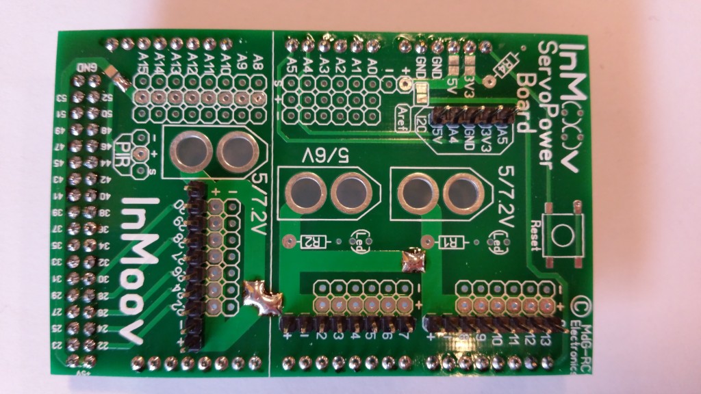
Soldering the little back connector option 3.3V or 5V to power last analog pins.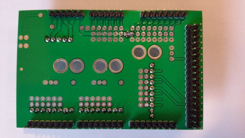
STEP4
Solder the push button.
STEP5
Step5 and 6 are optional. If you don’t plan to have finger sensors or some sensors connectors, please jump over to step7.
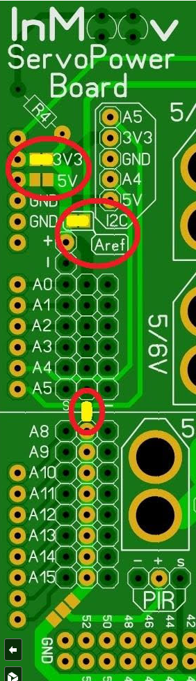
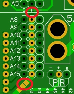
With the Analog circuit, you can make a choice between 3.3V or 5V…
3.3V selection:
(please notice, on the new version, that the Solder-Jumper between A5 row and A8 row is at the bottom side, close to the PIR connection!)
And if you want it to work with 3.3V, you also need the Aref and this must also be activated in the Sketch !
If you don’t use the Aref option, the resolution is not longer 0 to 1024 !
You might want to check this info: https://www.arduino.cc/en/Reference/AnalogReference
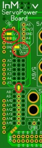
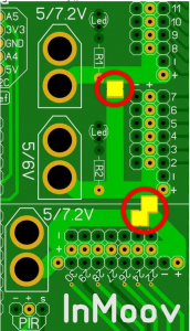
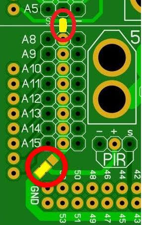
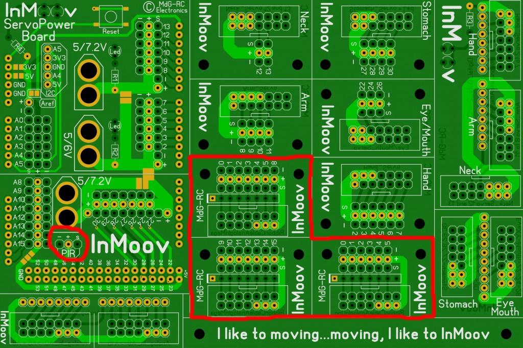
If you are using 3.3V for all your analog pins and you like to use a P.I.R. sensor…
If this this sensor needs 5V, you need to solder a solder-jumper as showed in the bottom red circle:
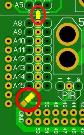
If the P.I.R. sensor works fine with 3.3V:
STEP6
Add the Analog headers for the finger sensors.
STEP7
Step7 is optional, therefore the next steps won’t show the leds and resistors. If you don’t want to add leds to your Nervo boards to illuminate the logo and to see when your board is under power, Please jump over to step8.
Otherwise, add and solder the various leds(5V) and resistors(Resistor 4700 ohm).


STEP8
Add and solder the connector headers on the three upper boards. (Only two boards are shown here, the third one is for the finger sensors.)
STEP9
Mount and solder the upper boards on the Nervo board.
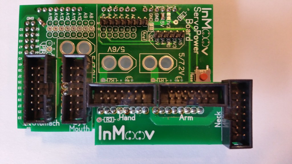
STEP10
If you have finger sensors, mount the third upper board( see step5 and 6).
STEP11
Solder the power yellow XT60 connectors.
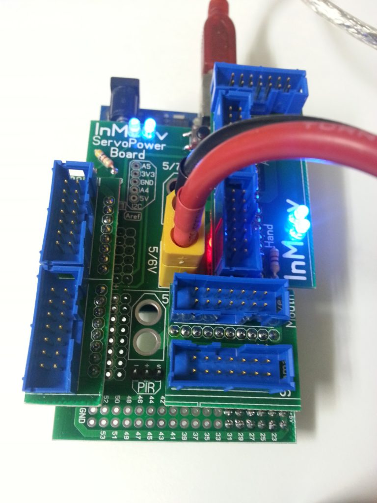
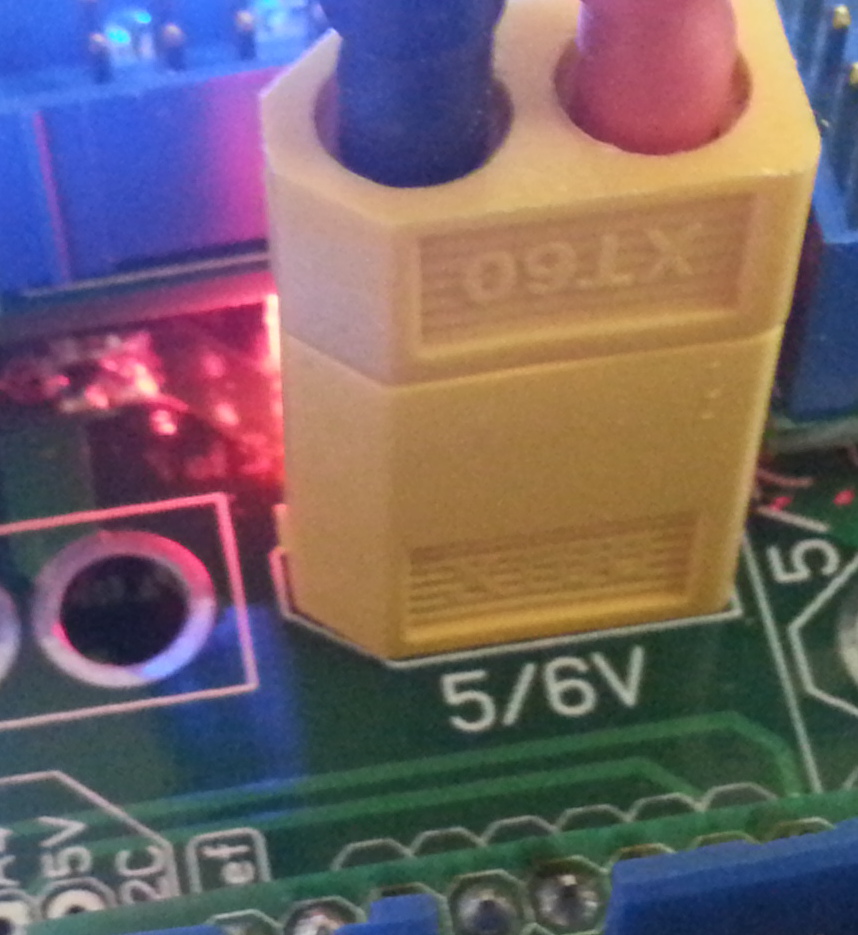
On the bellow picture they are blue and slightly different, this was a previous version.
If you have two Nervo Boards to power, you can add a XT60 connector in order to make a jumper cable.
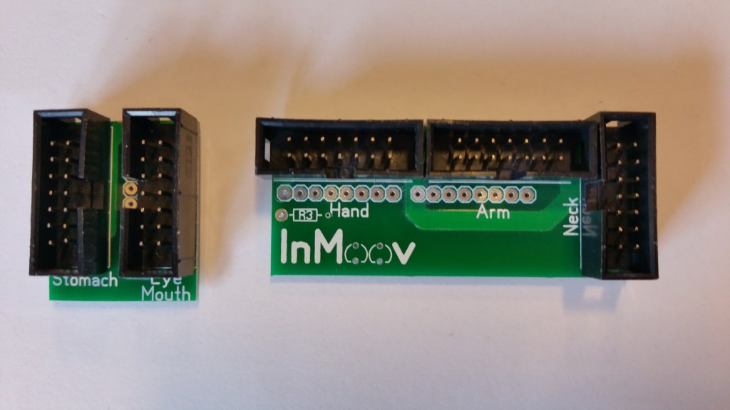
STEP12
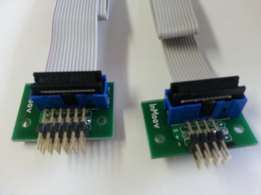
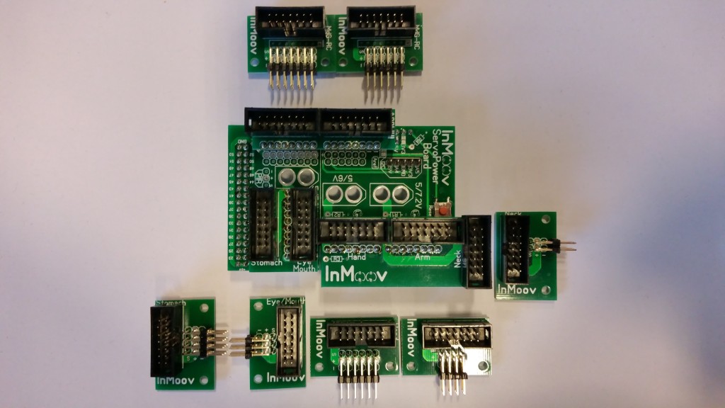
It’s now time to solder all the header IDC Socket and the Angle Male Pin Header to the mini breakout boards. Respect the numbers of pins needed per parts as shown on the bellow picture.
Below are the 5 necessary breakout boards: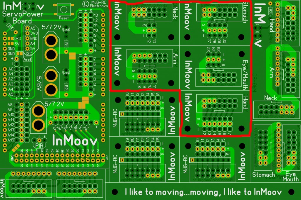
Bellow are the 3 optional finger sensor breakout boards. Only 2 are used. The third is a spare.
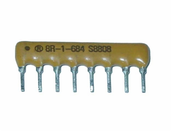
SIP resistor.
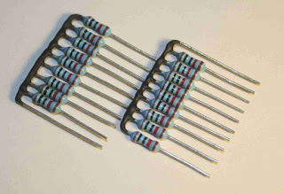
Standard resistor
The value depends, so it’s hard to give the correct value.
I think 100Kohm is a good value to start.

Adding the resistor for the finger sensors
STEP13
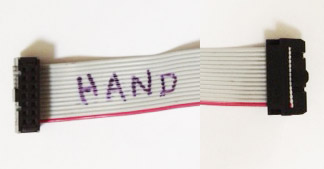
Fix the 14 Conductor Ribbon Cable to the Header Socket Connectors. (Notice: The 14 Conductor Ribbon Cable is not included in the Nervo board kit) It is very important to make sure to respect at all time the polarity of your ribbon, other wise you might burn your servos.
To respect the polarity, make sure your ribbon has a red line on its side. If not it is a good idea to use red sharpie pen and mark it.
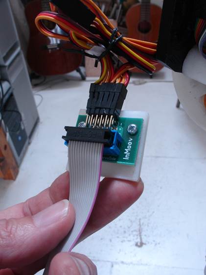
Here is how the connectors should be mounted on the ribbon with red line.
Be carefull not to get shortcut connections, this exemple below was badly assembled and the ribbon got very warm and could have melted.

STEP14
Once everything is soldered and ribbon cables are connected, Marten suggest to run a test with a multimeter.
Quote: « It’s better to check first the resistance between the Plus and GND connection(s) with a MultiMeter (Resistance mode) !
To do this:
Before mounting the Mega/Uno Nervo boards to the Arduino, measure between the Plus and GND Power input(s).
Everything is fine, when there is no resistance between these connections.
To find out where it’s wrong, disconnect step by step the NervoBoard at the Servo side…
And after each step, measure the Plus and GND connection(s) again, until there is no resistance any more.
In most cases, there’s something wrong with a flat-ribbon-cable. »
STEP15
Mount all the mini breakout boards as shown.
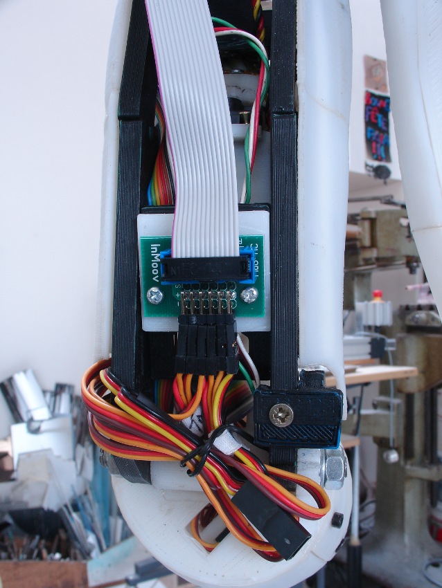
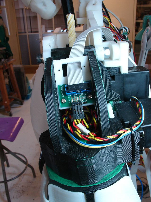
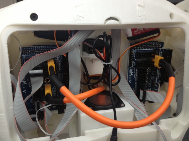
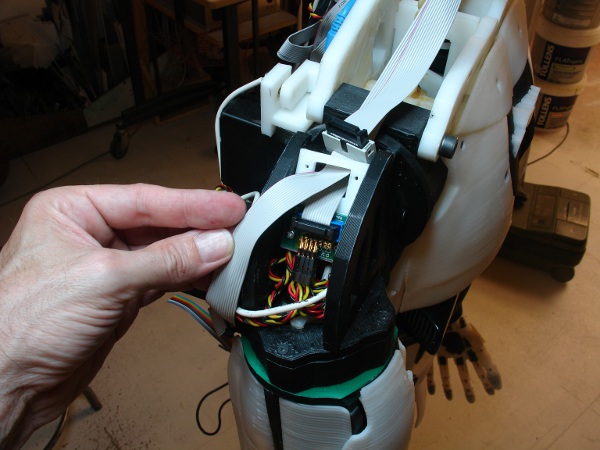
STEP16
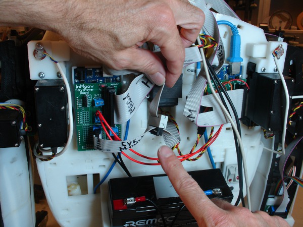
Fix your Arduino boards and Nervoboards as shown on the back of InMoov. There is no specific place to attach them.
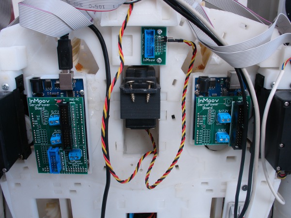
You can connect the two Nervo board power supply together, this is handy when using only one battery or one power supply.
Here is a xls file made by Lecagnois, which gives you the pins settings to test your connections to be sure all is soldered and mounted correctly:HE10.xls
You want to add a NeoPixel ring to your InMoov Nervoboard?? Follow this tutorial: HOWTO-Neopixel-diagram-&-configuration
You should be now ready to run some test with MyRobotLab.
Have fun with InMoov!!!