As I was not familiar to connectors for servos, I created my own connectors which work nicely and cost really cheap.
And since I have a 3D printer, I decided to make good use out of it.
If you buy or plan to get the Nervo board, you don’t need to make these connectors. This tutorial was done before, the Nervo Board was available.
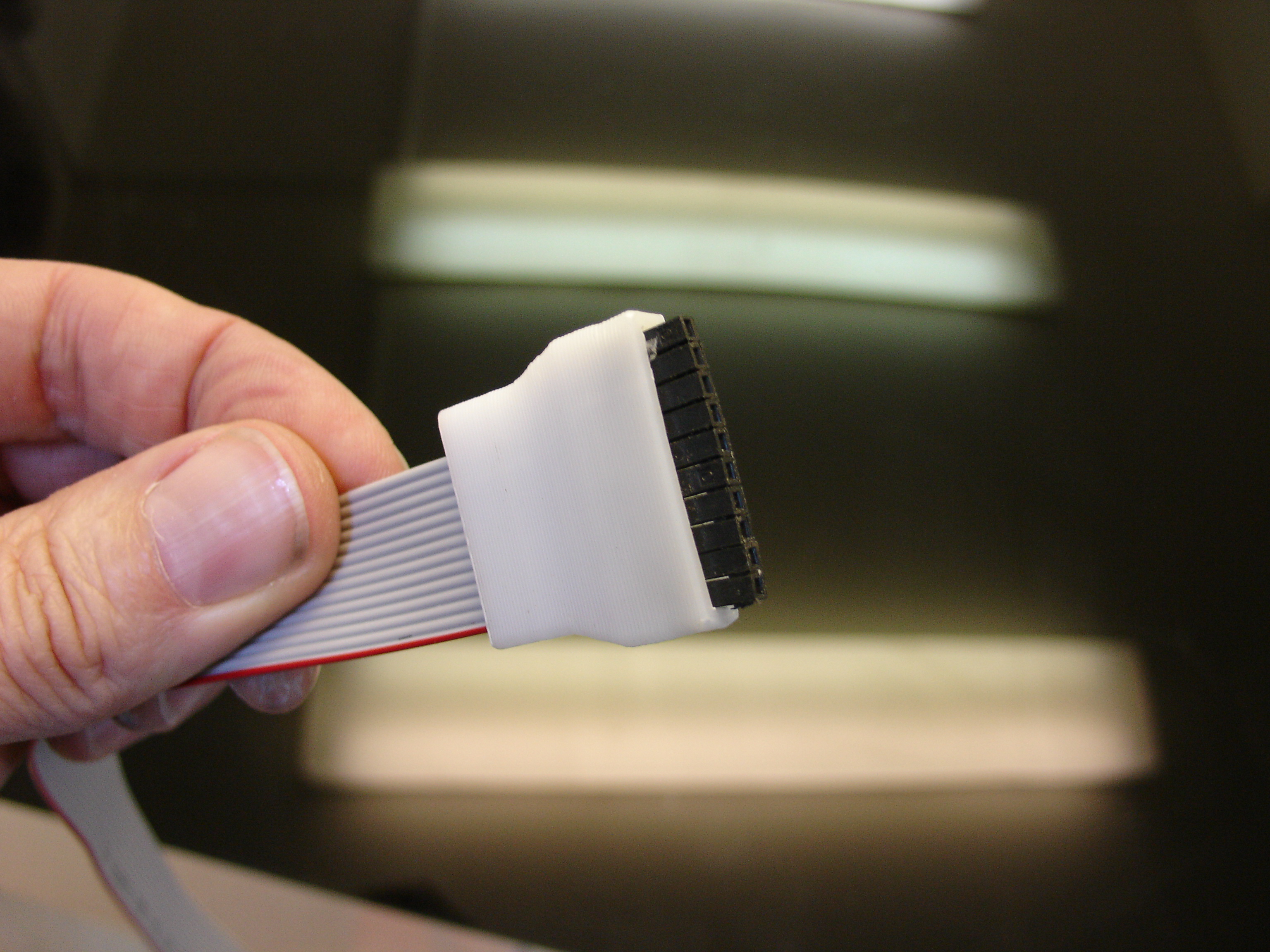
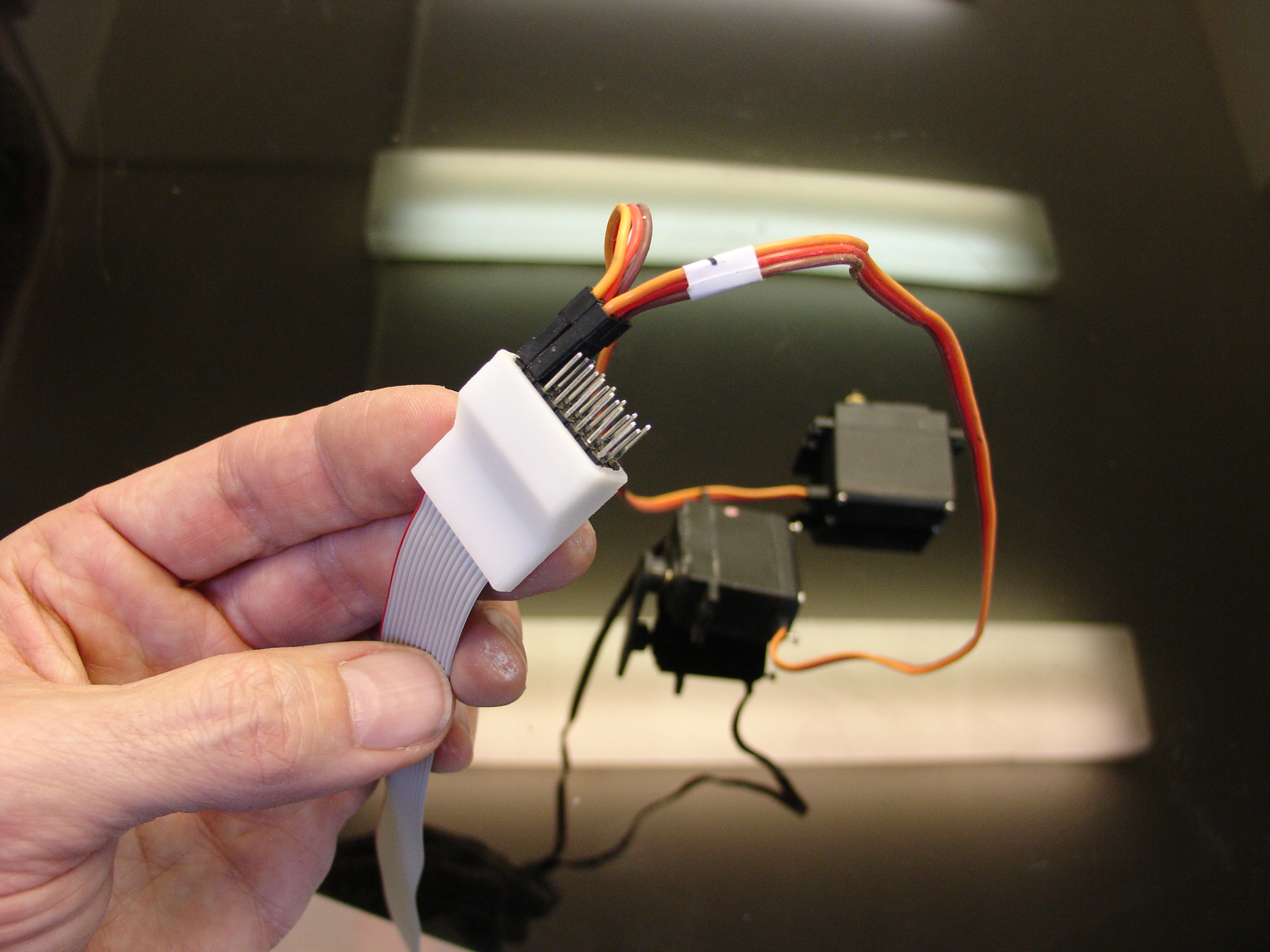
There is a different connector on each end of the ribbon, one side has male header pins on which you will connect 7 to 8 servos (hand and bicep), and the other side has female header pins to connect to the Power Supply Board.
You can use either ribbons with 14 or 16 wires.
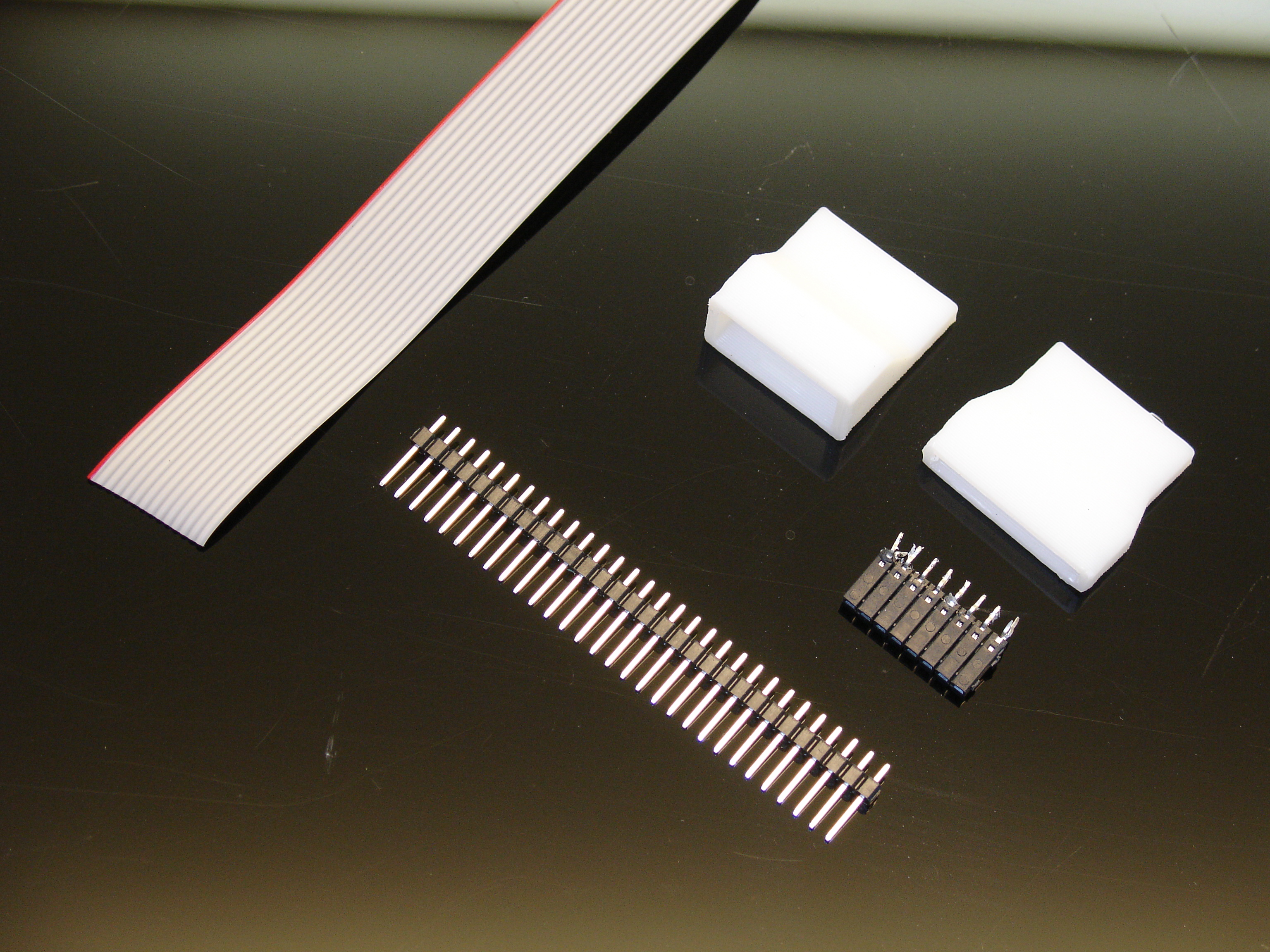
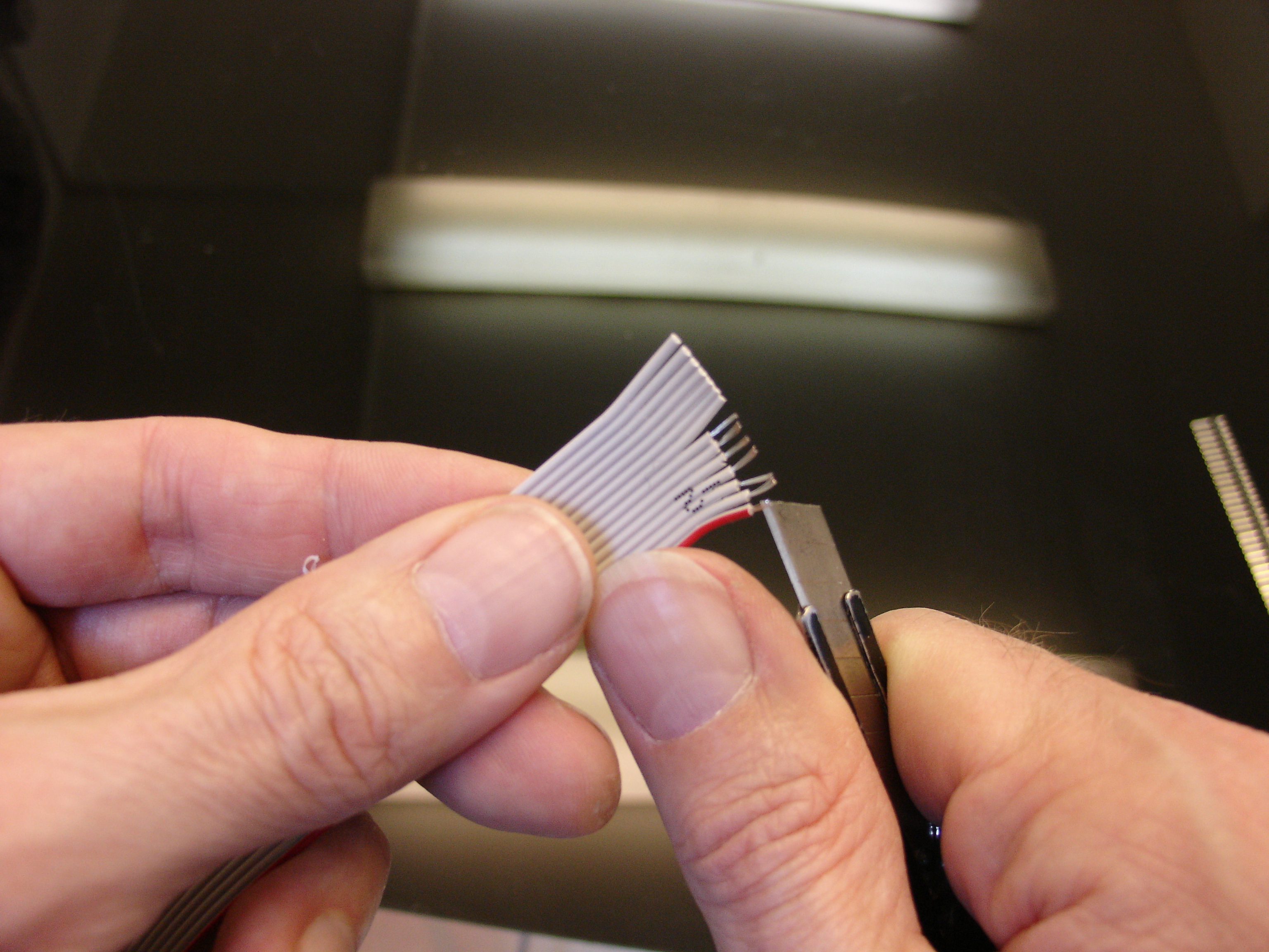
Before welding the wires, slide first the printed connectors in the correct direction.
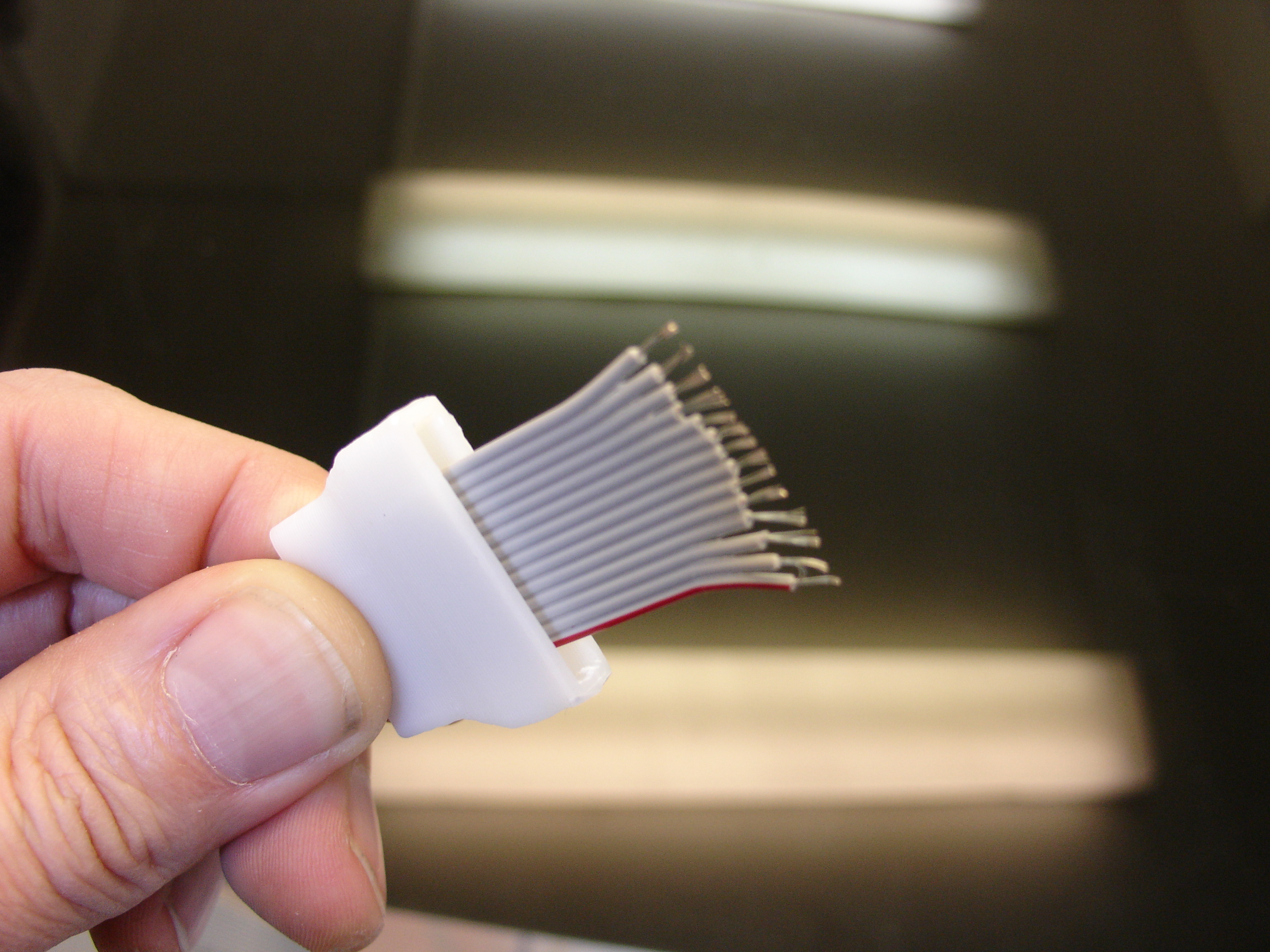
The red side of the ribbon will be our power supply reference. We want to have 3 wires for the VCC+, and 3 wires for GND. the rest will be for the PWM.
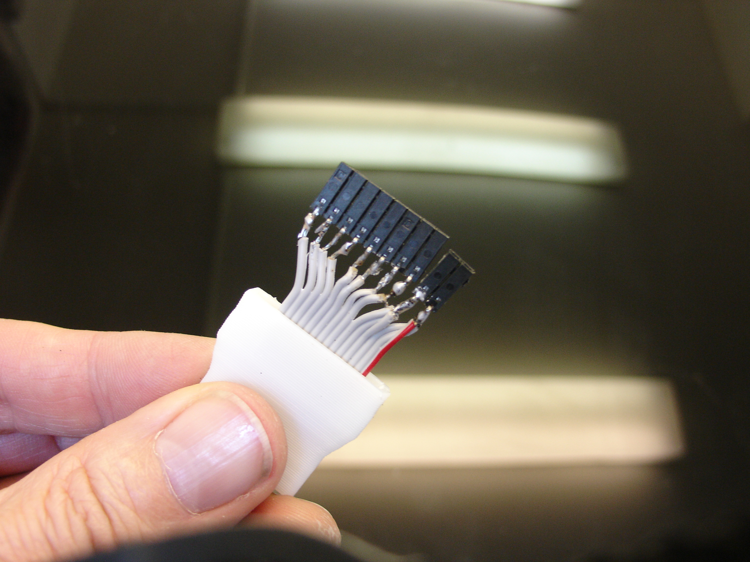
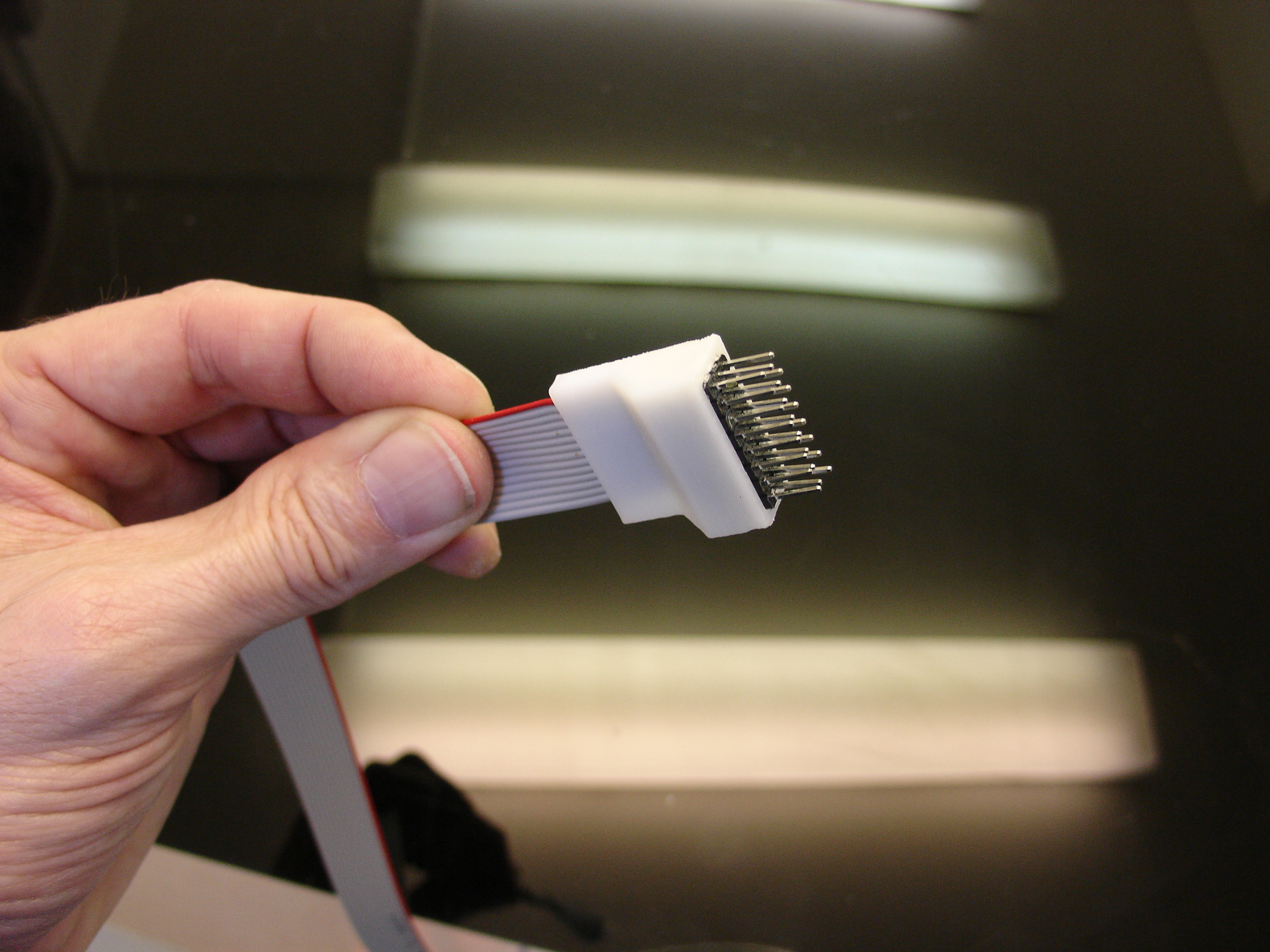
Welding the wires to the pins, specially on the male header pins is a bit difficult because the space between the pins is pretty small and narrow.
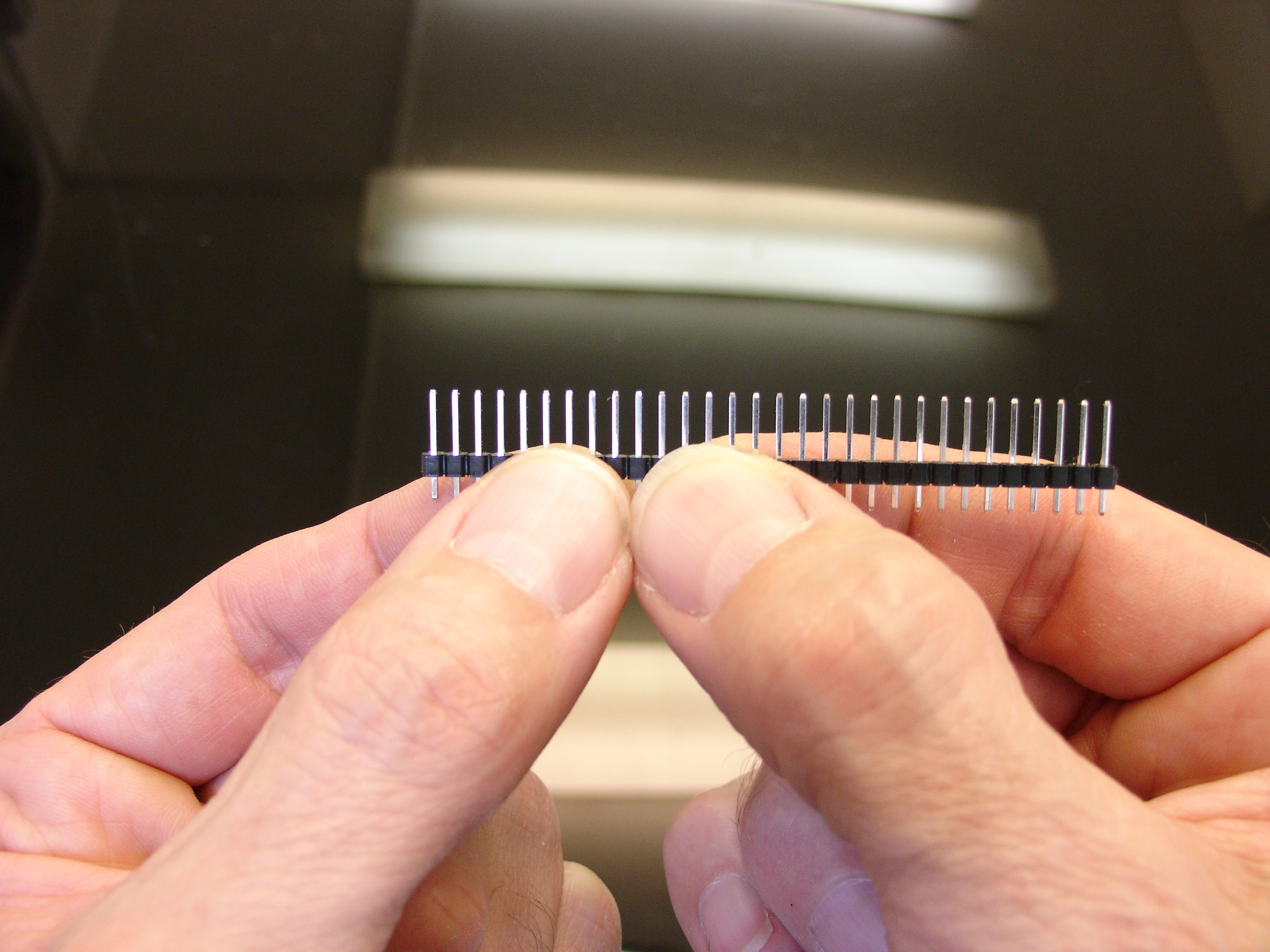
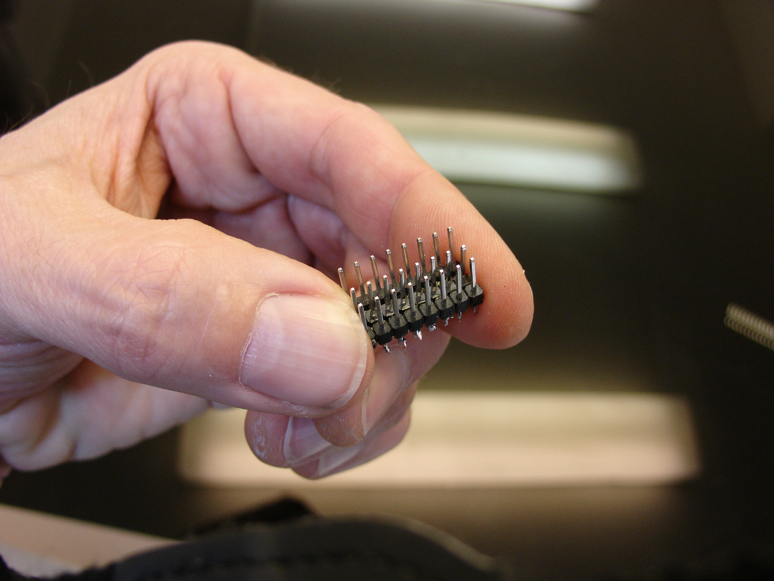 Glue the 3 headers line together with Epoxy glue.
You can see on this picture where my power supply side is and also which pins I have chosen for the PWM.
Once your weldings are correct and tested, you can glue with some epoxy the headers into the printed connectors. I had to push them hard inside, to make them fit.